Assembly Basics
description: …because to build a house, you must first lay its foundation.
🔤 Assembly Basics
Assembly
Assembly language at its basic is an symbolic language that directly ties a language machine can understand and a language that is easy for humans to understand.
An instruction like add rax, 1 is simpler than machine shellcode equivalent 4883C001 or binary machine code 01001000 10000011 11000000 00000001
There are different processor architectures and each needs a program to be written on different sets of instructions. This is where low-level languages like C come in.
C has a complier that compiles a source code to a variety of architectures without writing different source code for each.
Computer Architecture
The following is the Von Neumann Architecture of modern computers
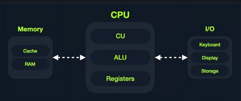
Memory
Memory is where the temporary data and instructions reside when a program is running/doing calculations. This is the first place a CPU goes to retrieve and process data. Very fast but also volatile
There are two types of memory:
- Cache
- Random Access Memory or RAM
Cache
Cache memory resides withing the CPU and is extremely fast compared to RAM as it runs on the same clock speed. However it is very limited in size and memory.
There are three levels of cache memory, sorted by their physical closeness to CPU
| Level | Explanation |
|---|---|
| Level 1 Cache | Usually in kilobytes, the fastest memory available, located in each CPU core. (Only registers are faster.) |
| Level 2 Cache | Usually in megabytes, extremely fast (but slower than L1), shared between all CPU cores. |
| Level 3 Cache | Usually in megabytes (larger than L2), faster than RAM but slower than L1/L2. (Not all CPUs use L3.) |
RAM
Ram is a larger cache memory and much slower than Cache memory. It’s also residing physically further from the CPU, hence used after Cache memory.
When a program starts, all of its data and instructions are loaded to the RAM(from storage) to be accessed whenever necessary by the CPU.
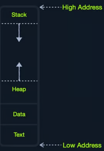
RAM is split into four main segments
| Segment | Explanation |
|---|---|
| Stack | Has a Last-in First-out (LIFO) design and is fixed in size. Data in it can only be accessed in a specific order by push-ing and pop-ing data. |
| Heap | Has a hierarchical design and is therefore much larger and more versatile in storing data, as data can be stored and retrieved in any order. However, this makes the heap slower than the Stack. |
| Data | Has two parts: Data, which is used to hold variables, and .bss, which is used to hold unassigned variables (i.e., buffer memory for later allocation). |
| Text | Main assembly instructions are loaded into this segment to be fetched and executed by the CPU. |
I/O Storage
Input/Output devices are storage unit, keyboard, screen etc. The processor can access and control IO devices using Bus Interfaces. These are metallic ‘highways’ on a PCB that help transmission of electrical charges as binary data.
Each Bus has a capacity of how much electric charge(or bits) it can carry at a given moment. This is usually a multiple of a nibble(half of a byte) up to 128-bits.
Bus interfaces are used to access memory and components outside the CPU. This is why there are countless bus interfaces around the CPU.
By speed here are memory components sorted
| Component | Speed | Size |
|---|---|---|
| Registers | Fastest | Bytes |
| L1 Cache | Fastest, after Registers | Kilobytes |
| L2 Cache | Fast after L1 | Megabytes |
| L3 Cache | Slower than all of the above | Megabytes |
| RAM | Slower than all of the above | GB-TB |
| Storage | Slowest | TB+ |
CPU Architecture
CPU is the main processing unit within a computer. The CPU contains the Control Unit(CU), which is in charge of moving and controlling data and there’s Arithmetic/Logic Unit(ALU), which is in charge of performing arithmetic and logical calculations as requested.
Efficiency of a CPU and which instructions it can run depends on its Instruction Set Architecture(ISA). RISC architecture is based on processing more simple instructions, which takes more cycles but each cycle is shorter and takes less power. CISC architecture is based on processing fewer, more complex instructions, which takes less instructions and fewer cycles but each instruction takes more time and power.
A clock speed refers to each tick given one cycle of an operation that it takes to process a basic instruction, like fetching an address or storing one.
The frequency of cycles is measured in Hertz. Example: CPU speed with 2.0GHz means that it can run 2 billion cycles every second(per core).
Instruction Cycle
An Instruction Cycle is the cycle it takes the CPU to process a single machine instruction It consists of four stages:
| 1. Fetch | Takes the next instruction’s address from the Instruction Address Register (IAR), which tells it where the next instruction is located. |
|---|---|
| 2. Decode | Takes the instruction from the IAR, and decodes it from binary to see what is required to be executed. |
| 3. Execute | Fetch instruction operands from register/memory, and process the instruction in the ALU or CU. |
| 4. Store | Store the new value in the destination operand. |
| An example: |
- Fetch the instruction from the
ripregister,48 83 C0 01(in binary). - Decode
48 83 C0 01to know it needs to perform anaddof1to the value atrax. - Get the current value at
rax(byCU), add1to it (by theALU). - Store the new value back to
rax.
each processor has its own set of instructions and corresponding machine code. So, each processor type has its Instruction Set Architectures, and each architecture can be further represented in several syntax formats
Instruction Set Architectures
ISA specifies the syntax and semantics of the assembly language. It consists of
- Instructions -
add rax, 1, mov rsp, rax, push rax - Registers -
rax, rsp, rip - Memory Addresses -
0xffffffffaa8a25ff, 0x44d0, $rax - Data Types -
byte, word, double word
There are two main ISA that are used widely:
- CISC - used by Intel and AMD processors
- RISC - used in ARM and Apple processors, in most smartphones and some laptops
Registers, Addresses and Data Types
Registers
CPU has a set of registers, which are the fastest components on any computer, because they are built within the CPU core. Regardless, registers are limited in size and can hold only a few bytes of data at a time. The following are the essential registers
| Data Registers | Pointer Registers |
|---|---|
| rax (primary) | rbp (Base pointer) |
| rbx (primary) | rsp (Stack pointer) |
| rcx (primary) | rip (Instruction Pointer) |
| rdx (primary) | |
| rdi (destination) | |
| rsi (source) | |
| r8 (secondary) | |
| r9 (secondary) | |
| r10 (secondary) |
Note: letter r at the beginning of registers denote that these are 64-bit registers. letter e denotes that they are 32-bit registers . Like eax or ebp
Data Registers are used for storing instructions/syscalls.
Pointer Registers are used to store specific memory address pointers rbp - points to beginning of the Stack rsp - points to the current location within the Stack rip - holds the address for the next instruction
Each register can be further divided into smaller sub-registers containing lower bits: 8-bits, 16-bits, 32-bits
| Size | Example |
|---|---|
| 8-bit | al |
| 16-bit | ax |
| 32-bit | eax |
| 64-bit | rax |
Memory Addresses
Memory is segmented into memory regions, like the Stack, Heap and other program and kernel-specific regions. Each segment has specific read, write, execute permissions that specifies what can be done in that segment.
whenever an instruction is called, the first step is to fetch the instruction from the address it’s located at. Several types of address fetching in x86
| Addressing mode | Explanation | Example |
|---|---|---|
| Immediate | The value is given withing the instruction | add 2 |
| Register | The register that holds the value is given to instruction | add rax |
| Direct | The full address is given in the instruction | call 0xffffffffaa8a25ff |
| Indirect | A reference pointer is given in the instruction | call 0x44d000 or call [rax] |
| Stack | Address on top of the stack is passed to the instruction | add rsp |
Endianness
An address endianness is the order of its bytes in which they are stored or retrieved from memory. There are two types of endianness: Little-Endian and Big-Endian. With Little-Endian processors, the little-end byte of the address is retrieved right-to-left Example: an address 0x0011223344556677 will be stored in reverse -> 0x7766554433221100
With Big-Endian processors, the big-end byte is retrieved left-to-right
In little endian, if we were to push an address or a string with Assembly, we would have to push it in reverse. For example, if we want to store the word Hello, we would push its bytes in reverse: o, l, l, e, and finally H.
Data Types
x86 architecture supports several data types
| Data type | Length |
|---|---|
| byte | 8 bits |
| word | 16 bits |
| dword | 32 bits |
| qword | 64 bits |
Assembly File Structure
         global  _start

         section .data
message: db      "Hello"

         section .text
_start:
         mov     rax, 1
         mov     rdi, 1
         mov     rsi, message
         mov     rdx, 18
         syscall

         mov     rax, 60
         mov     rdi, 0
         syscall
In the example above we have
| Section | Explanation |
|---|---|
global _start | This is a directive for the code to start executing at the _start label defined below |
section .data | This is a data section, which should contain all of the variables |
section .text | This is a text section containing all of the code that should be executed |
Directives
An assembly code runs line-by-line. Directives like global _start indicates the machine where to start processing instructions. So, the machine goes to the _start label and starts executing the instructions there.
Variables
The .data section holds variables that will be loaded into memory once the program is run
Variables can be defined using db for a list of bytes, dw for a list of words and dd for a list of digits and so on. it is also possible to label variables for later usage
| Instruction | Description |
|---|---|
db 0x0a | defines the byte 0x0a which is a newline |
message db 0x41, 0x42, 0x43, 0x0a | Defines the label message => abc\n |
message db "Hello World!", 0x0a | Defines the label message => Hello World!\n |
| In an example below |
section .data
    message db "Hello World!", 0x0a
    length  equ $-message
$ token indicates the current distance from the beginning of the current section.
Code
.text section holds all assembly instructions and loads them to the text memory segment. Once all instructions are loaded, then the processor starts executing them in order.
The text segment within the memory is read-only, so we cannot write any variables within it.
The data section is read/write, which is why we write our variables to it.
Assembly basic instructions
Moving data around
Data movement is one of the fundamental instructions in any assembly program. The main Data Movement instructions are:
| Instruction | Explanation | Example |
|---|---|---|
mov | Move data or load immediate data | mov rax, rip |
lea | Load an address pointing to the value | lea rax, [rsp+5] |
xchg | Swap data between two registers or addresses | xchg rax,rbx |
Example 1: moving data to a register
global _start

section .text
_start:
 mov rax, 0 ; move value 0 to rax
 mov rbx, 1 ; move value 1 to rbx
 mov al, 1  ; move 1-byte into a 1-byte register(al)
assembling asm.s using nasm nasm -f elf64 asm.s && objdump -M intel -d asm.o
Example 2: moving pointer values
global _start

section .text
_start:
 mov rax, rsp
 mov rax, [rsp]
Square brackets [] tells nasm to move whatever the value is at address rsp to rax
Example 3: Loading value pointers using lea
global _start

section .text
_start:
 lea rax, [rsp+10] ; loads rsp+10 address space to rax
 mov rax, [rsp+10] ; loads value at rsp+10 address space to rax
Arithmetic Instructions
Arithmetic instructions are split in Unary and Binary operands.
Unary
Unary instruction take only one argument
| Instruction | Explanation | Example |
|---|---|---|
inc | Increment by 1 | inc rax = rax++ |
dec | Decrement by 1 | dec rax = rax-- |
Binary
Binary instruction, namely takes two arguments
| Instruction | Explanation | Example |
|---|---|---|
add | Add both operands | add rax, rbx |
sub | Subtract Source from Destination rax = rax - rbx | sub rax, rbx |
imul | Multiply both operands | imul rax, rbx |
| result is always stored in the destination register. source stays intact. |
Bitwise
Bitwise instructions work on the bit level
| Instruction | Explanation | Example |
|---|---|---|
not | Bitwise NOT(inverts all bits) | not rax |
and | Bitwise AND(if both bits are 1 -> 1, if both 0 -> 0) | and rax, rbx |
or | Bitwise OR(if either is 1->1, if both 0->0) | or rax, rbx |
xor | Bitwise XOR(if bits are the same -> 0. if different -> 1) | xor rax, rbx |
global _start

section .text
_start:
    xor rax, rax ; 0
    xor rbx, rbx; 0
    add rbx, 15; rbx = 0x0F
    xor rbx, 15; 0
Program Control Instructions
Control instructions allows to change the flow of the program and direct it to another line. We have Directives, Loops, Branching, Function Calls
Loops
A loop in assembly is a set of instructions that repeat for rcx times.
global _start

section .text
_start:
        xor rax, rax ; rax = 0
        xor rbx, rbx ; rbx = 0
        inc rbx      ; rbx = 1
        mov rcx, 10  ; loop 10 times

loopFib:
        add rax, rbx ; get the next number
        xchg rax, rbx; swap values
        loop loopFib ;
In the example above rcx register in mov rcx, 10 is a general-purpose register, but for loop it has a special purpose.
loop checks rcx value each time that loop block executes and decreases rcx value each time. This loop runs until rcx is 0.
How does loopFib gets executed? loopFib: is just a label which gets translated to an address of add rax, rbx at runtime. While loop loopFib tells assembly where to jump at each iteration. This loop instruction checks that rcx>0 value before executing another loop.
Branching
Branching allows jump-ing to any location in the program if a condition is met. The most basic branching instruction is jmp which will always be triggered no matter the conditions.
An example
global  _start

section .text
_start:
    xor rax, rax    ; initialize rax to 0
    xor rbx, rbx    ; initialize rbx to 0
    inc rbx         ; increment rbx to 1
    mov rcx, 10
loopFib:
    add rax, rbx    ; get the next number
    xchg rax, rbx   ; swap values
    jmp loopFib
In this example, even though mov rcx, 10 is present, it won’t affect jmp loopFib because jmp is an unconditional instruction and will continue running the loop forever.
Conditional Branching
| Instruction | Explanation |
|---|---|
| jz | DST == 0 |
| jnz | DST != 0 |
| js | DST < 0 |
| jns | DST >= 0 |
| jg | DST > SRC |
| jge | DST >= SRC |
| jl | DST < SRC |
| jle | DST <= SRC |
Branching is not only done with jumping. It can also be combined with other instructions like mov with CMOVcc and SETcc. |
An example of mov rax, rbx but on the condition of == 0 cmovz rax, rbx Similarly for < cmovl rax, rbx
Similarly for set setz rax
RFLAGS
RFLAGS(are 64-bit) register sets the necessary flags to either 0 or 1 depending a certain condition is met. For example, if sub instruction resulted in a negative value, then the SIGN FLAG SF will be set to 1. If dec instruction resulted in 0, then ZERO FLAG ZF will be set to 1 and so on.
There are several RFLAGS that are present in assembly programs, each with its own flag bit.
| Bit location | Label | Explanation |
|---|---|---|
| 0 | CF | Carry Flag |
| 1 | Reserved | |
| 2 | PF | Parity Flag |
| 3 | Reserved | |
| 4 | AF | Auxiliary Carry Flag |
| 5 | Reserved | |
| 6 | ZF | Zero Flag |
| 7 | SF | Sign Flag |
| 8 | TF | Trap Flag |
| 9 | IF | Interrupt Flag |
| 10 | DF | Direction Flag |
| 11 | OF | Overflow Flag |
| 12-13 | IOPL | I/O Privilege Flag |
| 14 | NT | Nested Task |
| 15 | Reserved | |
| 16 | RF | Resume Flag |
| 17 | VM | Virtual-x64 Mode |
| 18 | AC | Access Control |
| 19 | VIF | Virtual Interrupt Flag |
| 20 | VIP | Virtual Interrupt Pending |
| 21 | ID | Identification Flag |
| 22-63 | Reserved |
RFLAGS - 64 bit EFLAGS - 32 bit FLAGS - 16 bit
Important flags
- The Carry Flag
CF: Indicates whether we have a float. - The Parity Flag
PF: Indicates whether a number is odd or even. - The Zero Flag
ZF: Indicates whether a number is zero. - The Sign Flag
SF: Indicates whether a register is negative.
global  _start

section .text
_start:
    xor rax, rax    ; initialize rax to 0
    xor rbx, rbx    ; initialize rbx to 0
    inc rbx         ; increment rbx to 1
loopFib:
    add rax, rbx    ; get the next number
    xchg rax, rbx   ; swap values
    cmp rbx, 10  ; do rbx - 10
    js loopFib  ; jump if result is <0
in the example above, cmp instruction has been added. All it does is subtract second argument from first and set necessary flags in RFLAGS register. Then jump instruction checks flag condition and continues accordingly. In this case after first number is calculated cmp rbx, 10 will result in -9. js will continue loop since its condition is UNTIL DST < 0
Functions
The Stack
The Stack is a segment of memory allocated for each program to store data in. It is used to temporarily store and retrieve data. Top of the stack is referred by the Top Stack Pointer rsp and bottom is referred as Base Stack Pointer rbp.
Data can either be pushed or pop’d from the stack. push Copies the specified register/address to the top of the stack. pop moves the item at the top of the stat to the specified register/address.
The stack has Last-in First-out (LIFO) design. This means we can only pop out the element that is at the top of the stack. If we push five more elements on top of it, we’ll have to pop all of them before accessing that last element.
Before calling functions or syscalls we need to save data to the stack. Otherwise the data will be lost. For example if we wanted to retain the current value at rax and run a syscall, we would first push rax to the stack and then call the function.
Using the stack is very simple. The only thing we should keep in mind is the order we push our registers and the state of the stack to safely restore our data and not restore a different value by pop when a different value is at the top of the stack.